The FieldScout app allows device readings from TruFirm and TDR devices to be gathered, stored and displayed within the app itself. There are 2 general modes for organizing data:
- Grid mode
- Freeform mode (Pro only)
Grid Mode
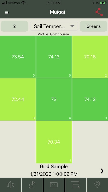
Grid mode enables the user to define a named “grid” that covers the area where measurements are being gathered. This grid may be any dimension from 1×1 to 5×5. FieldScout Pro users also have the option of overlaying the grid on top of a satellite map view.
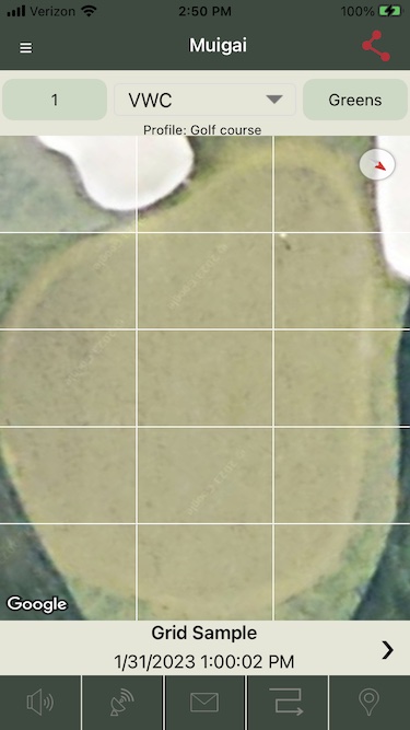
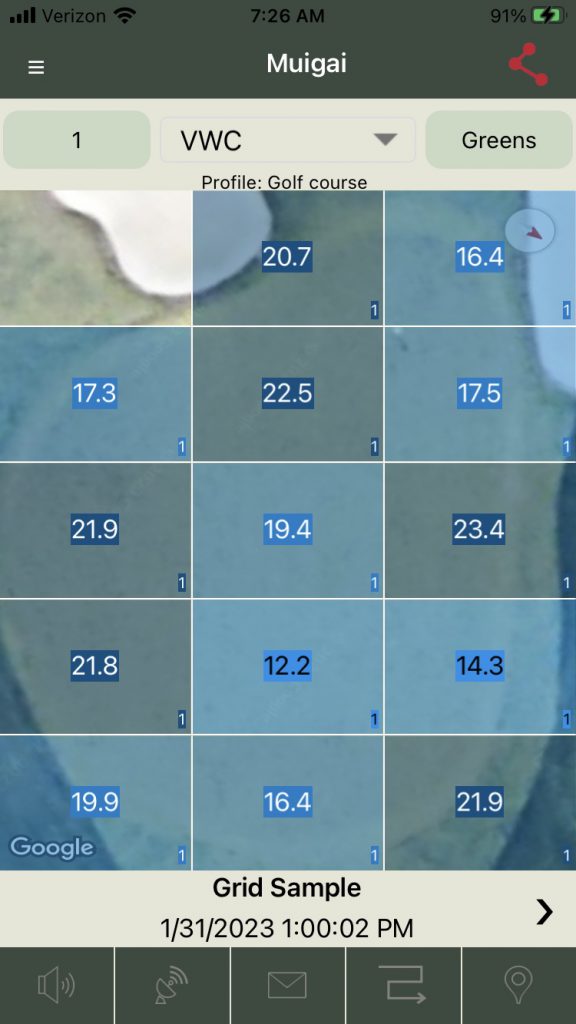
The user selects the zone within the grid where they are taking readings. The readings are averaged and displayed on the grid as shown in Figure 3 (Basic mode) and Figure 4 (Pro mode):
Freeform Mode (Pro-only feature)
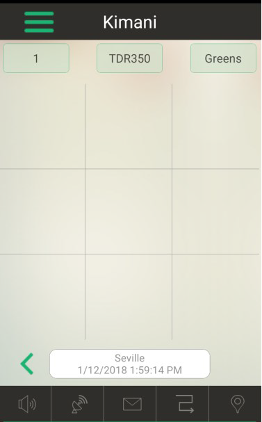
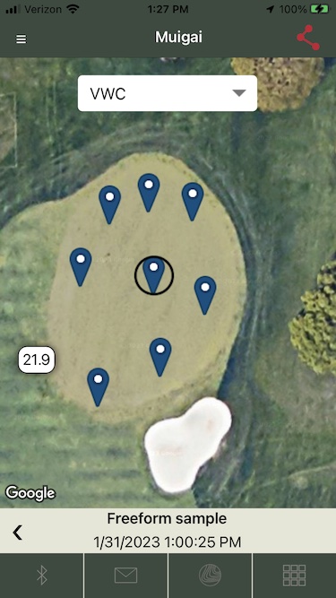
Freeform Mode data is displayed on a satellite map using the GPS location where the reading is taken (Figure 1).
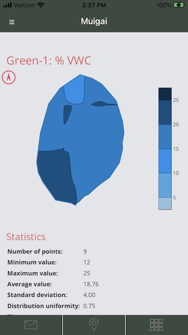
The user also has the option of viewing the data using a “contour” view for surfaces defined on SpecConnect (Figure 2).
Creating Grids and Surfaces
Although Grids may be created using the FieldScout app itself, users may find it more convenient to create Grid definitions using the SpecConnect portal Grid Editor and importing those definitions into the app. Freeform surfaces can only currently be created using the SpecConnect portal Surface Editor.
Creating Grids Definitions using the SpecConnect Grid Editor
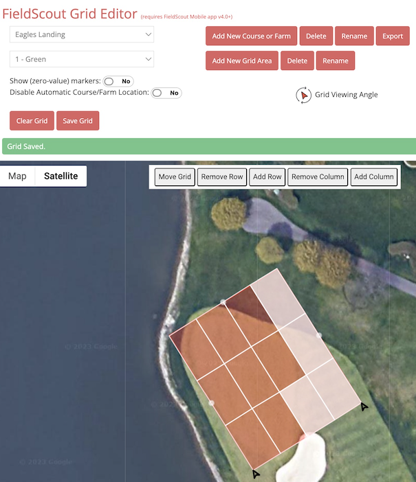
To use the SpecConnect Grid Editor, navigate to FIELDSCOUT >> GRID EDITOR on the left menu. From there follow these steps to create a grid definition:
- Select or Add a new course or farm
- Select or Add a new grid area name, e.g. Green, Tee, Field1. If you are defining a grid for a golf application, you should also specify a hole number (1, 2, …).
- Locate the grid…
- If you are creating a new grid area, position the map to the location where the desired grid area is to be created and click on the map. At this point a 3×3 grid will be displayed on the map centered at the location where you have clicked.
- If you are editing an existing grid area, the map will move to the location where the grid has previously been located.
- At this point you can use the buttons on the map to refine the grid definitions:
- Move Grid (once clicked, you will be able to drag the grid to new location)
- Remove Row
- Add Row
- Remove Column
- Add Column
- Rotate the grid by clicking on the Grid View Angle icon
 and moving the slider to find the desired angle orientation of the grid. Once satisfied, click the icon again to return to the full map.
 - Click on any of the zone regions with the grid to alternatively exclude/include that part of the grid as a valid region within the grid. The clicked zone becomes shade when it is excluded.
- Save the resultant Grid definition using the Save Grid button (or Clear Grid to start again)
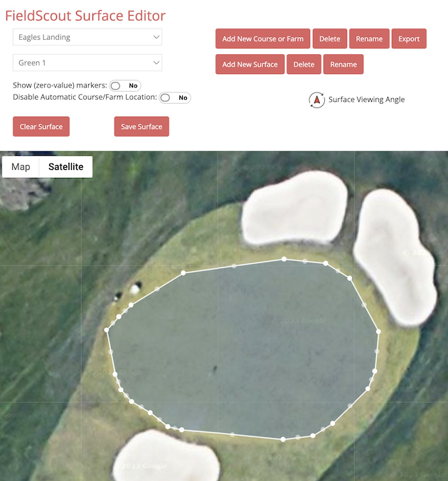
Creating Freeform Surface Definitions using the SpecConnect Surface Editor
The SpecConnect Surface Editor is used to define surface definitions to geographically group freeform readings to derive contour data displays. To use the Surface Editor, navigate to FIELDSCOUT >> SURFACE EDITOR on the left menu. From there follow these steps to create a grid definition:
- Select or Add a new Course or Farm
- Select or Add a new Surface
- Locate the surface…
- If you are creating a new Surface, position the map to the location where the desired surface is to be created and click on a location on the outer rim of the surface to be defined. Drag the pencil to roughly define the perimeter of the surface.
- If you are editing an existing surface, the map will move to the location where the surface has previously been defined.
- Drag and drop the surface handles to refine your definition and/or move the entire surface itself.
- Save the resultant Surface definition using the Save Surface button (or Clear Surface to start again)